
Engineering
Evidence from programmes in motion.
Demonstrators, test programmes and the tools built through them. This is where methods meet physical hardware, programme gates and results as they become available.
Flying Laboratory
REAH's physical test platform for turning thermal, propulsion, power and component-substitution assumptions into measured engineering evidence under representative Gulf operating conditions.
Platform — Pusher-configuration gyrocopter testbed
Rotax Gyrocopter Cooling Demonstrator
An open engineering study of cooling-system performance on a Rotax-powered gyrocopter in hot-climate operation — methodology, simulation and planned validation, published as the work happens.
Platform — Rotax-powered gyrocopter
Tools
Engineering methods, made reusable.
The software, workflows and test systems developed through the work above. Every repeated analysis is a candidate to become a tool.
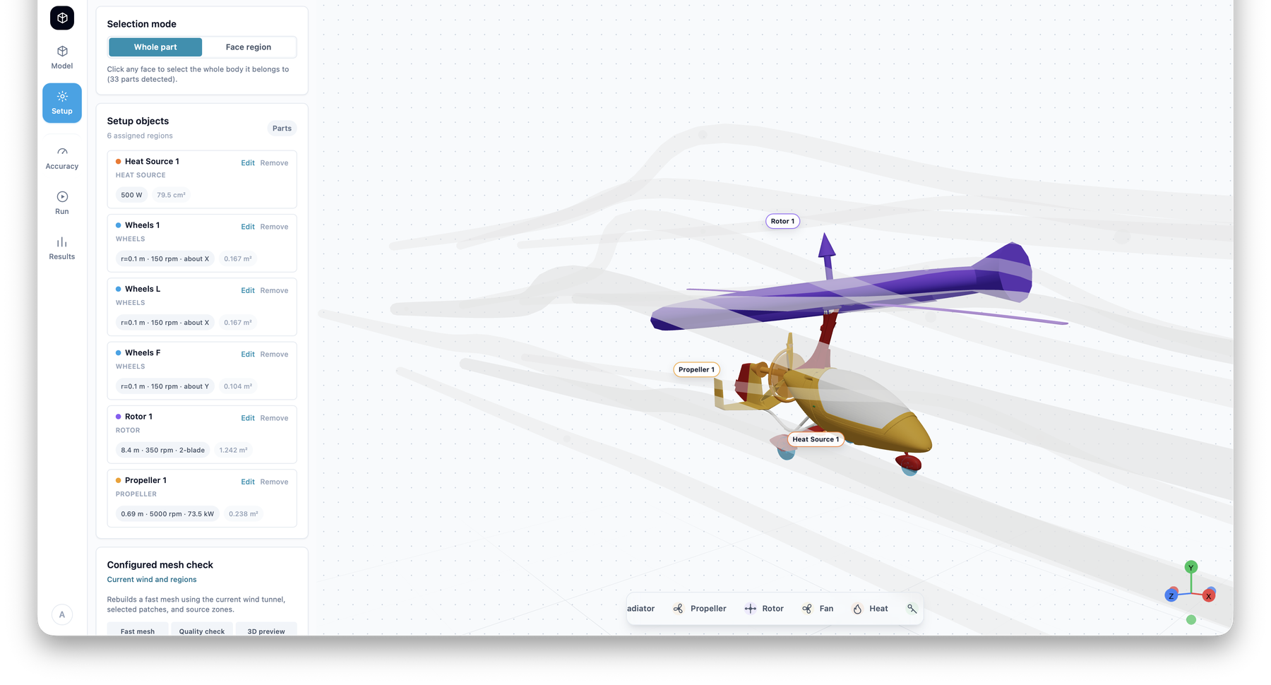
REAH CFD Studio
Our internal simulation front-end: CAD upload, flow and heat setup, accuracy selection, solve and results review for internal- and external-flow cases. Used daily on our own engineering work.
Workflow — REAH CFD Studio
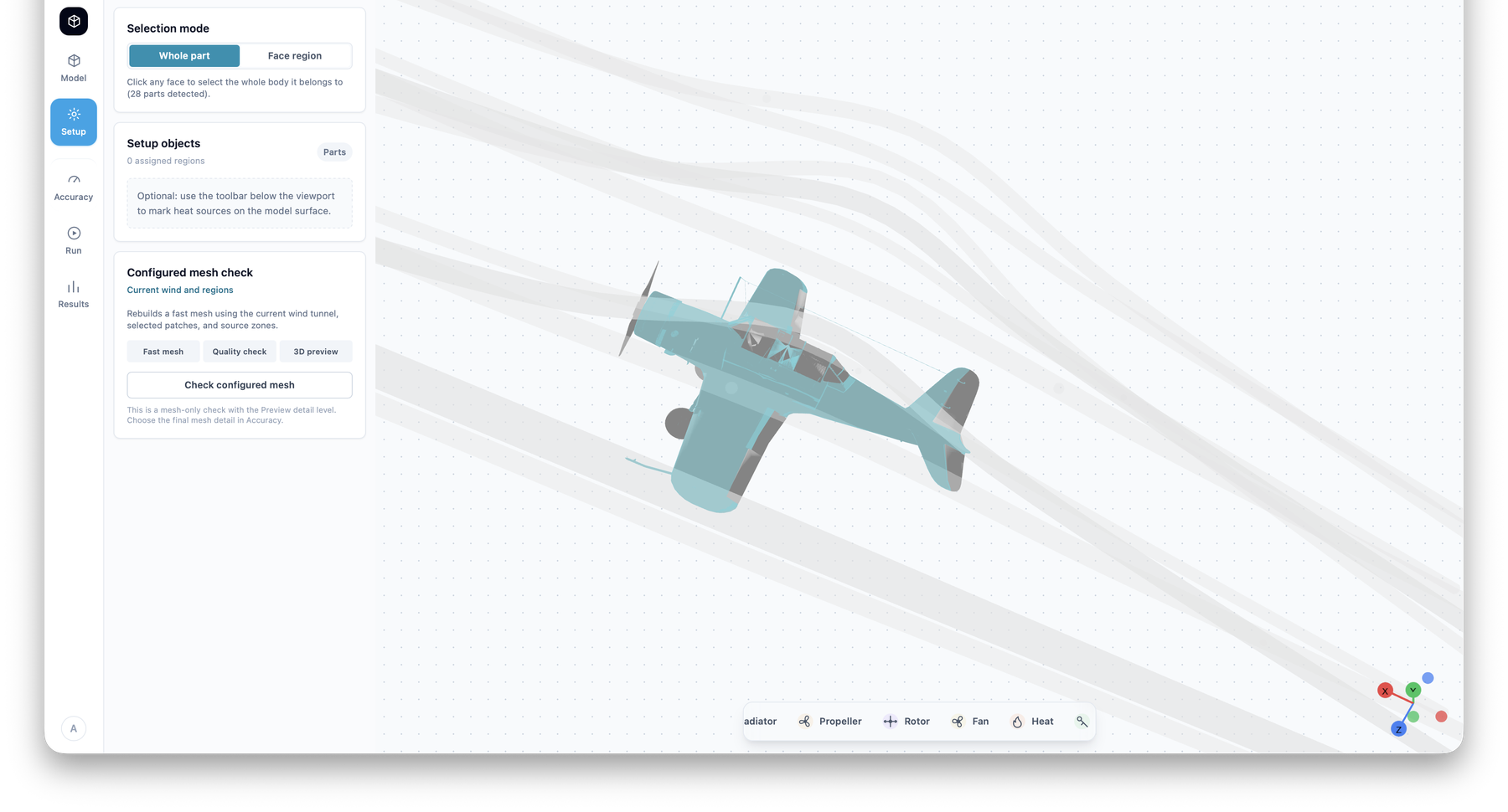 01
01Setup — model regions selected, mesh checks configured before the run.
02Regions — propeller, rotor, wheel and heat-source assigned on the model.
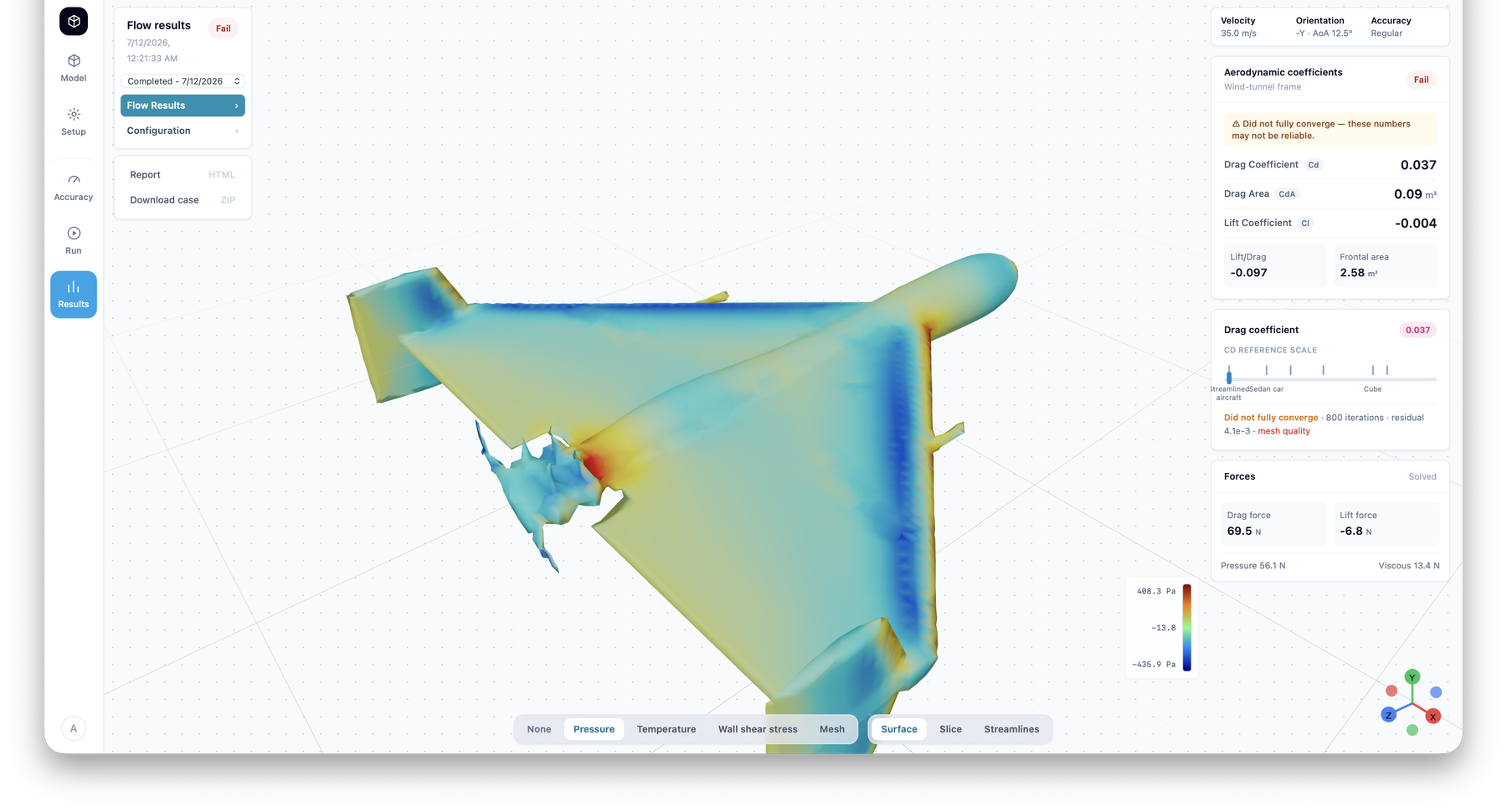 03
03Results — surface pressure and aerodynamic coefficients. This run did not fully converge; the tool flags it rather than hiding it.
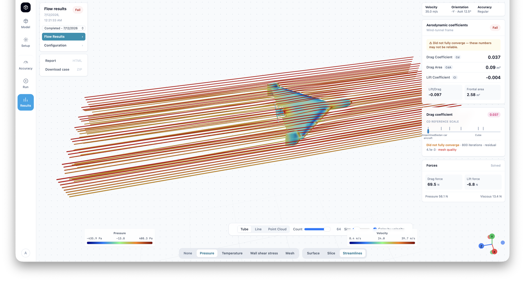 04
04Streamlines — flow-field review for the same case, development output rather than validated aerodynamic data.
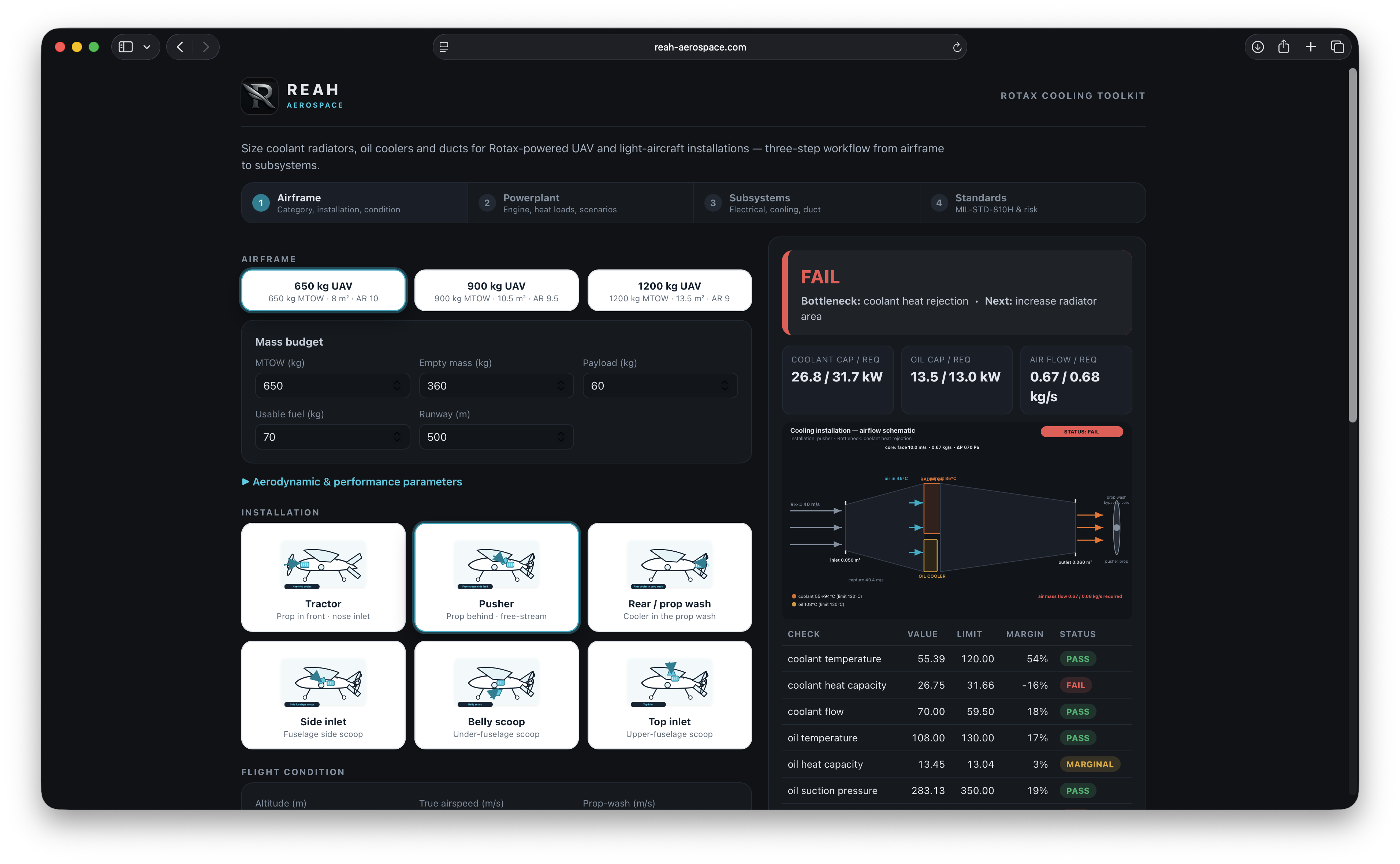
Rotax Cooling Toolkit
Physics-based sizing of coolant radiators, oil coolers and ducts for Rotax-powered installations — a pass/fail verdict per check, with margins stated. Engineering estimate only; calibrated against test data before any certification use.
Aircraft thermal-system models
1D flow-network and heat-budget models of complete cooling installations, built to be correlated against ground- and flight-test data.
Engine-bay CFD workflows
Version-controlled, reproducible OpenFOAM case templates for engine-bay airflow, duct losses and recirculation assessment.
Flight-test data acquisition
Sensor, logging and telemetry packages for instrumented test campaigns on our flying laboratory.
Propeller-slipstream models
Actuator-disk and body-force models of slipstream interaction with cooling inlets and exits, for tractor and pusher configurations.
Experimental cooling components
Prototype ducts, inlets and cooler installations designed for instrumented evaluation on the flying laboratory.
How these tools are built is described on the Digital Engineering Tools capability page.
Working on a similar problem?
The methodology in these programmes applies directly to customer aircraft.